
 English
 русский
 Español


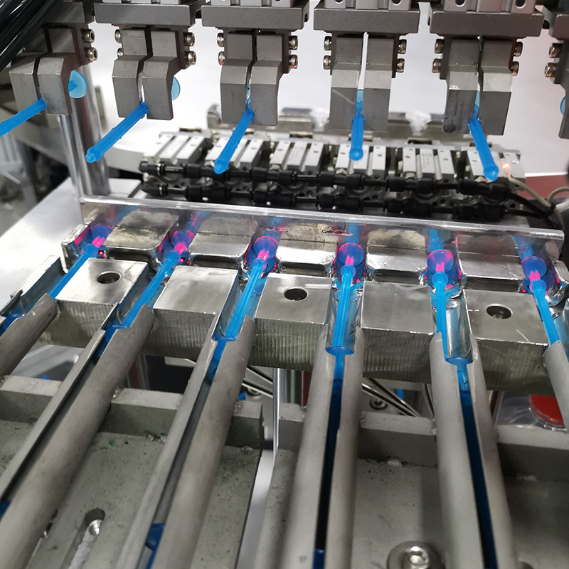
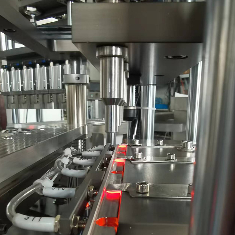
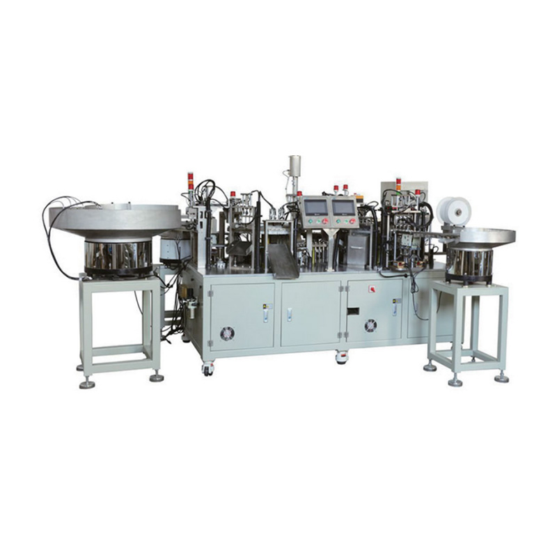
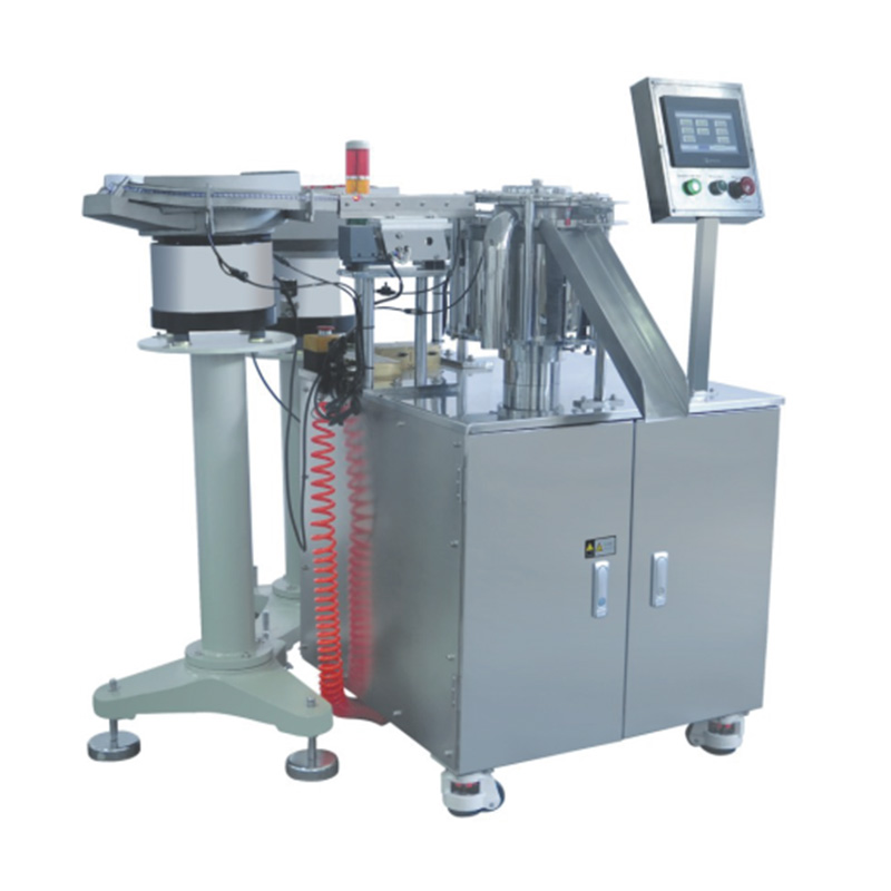
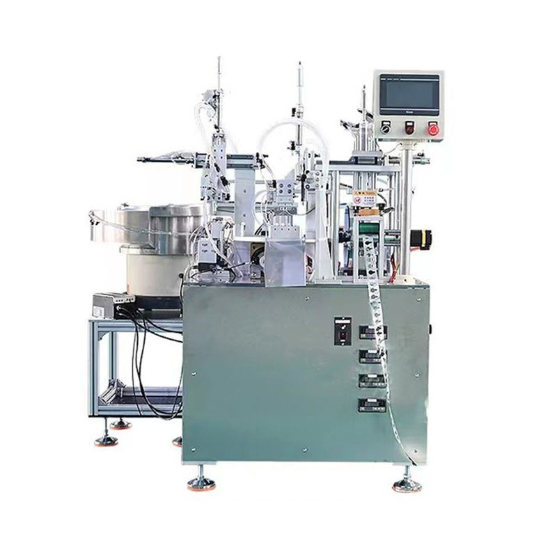
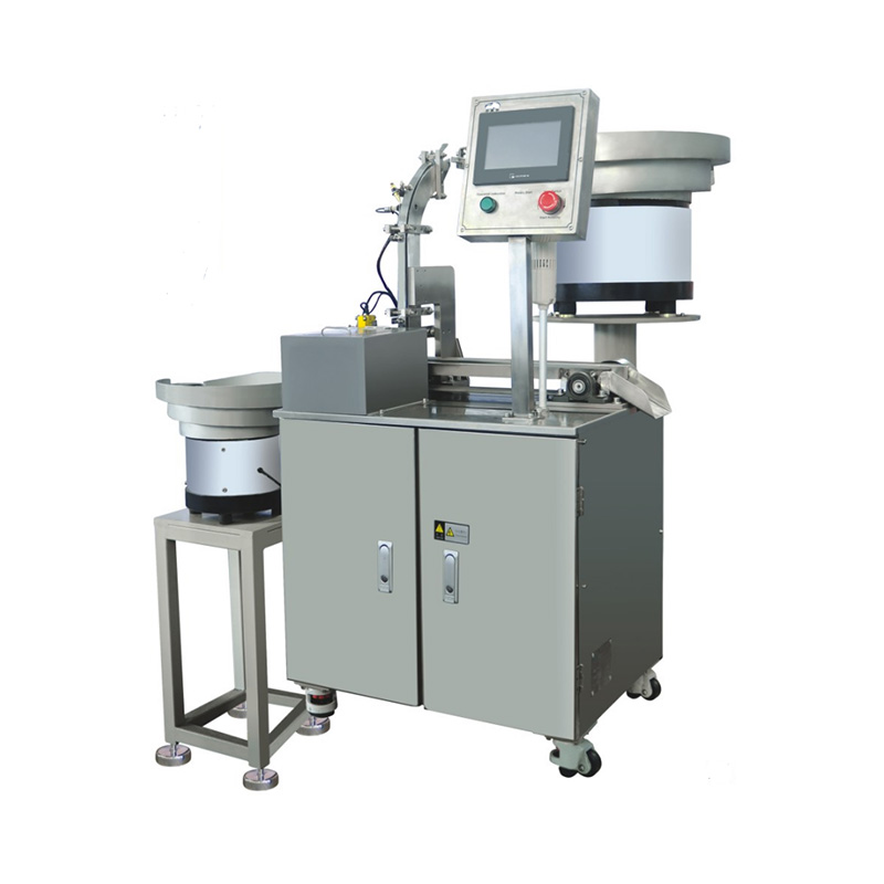
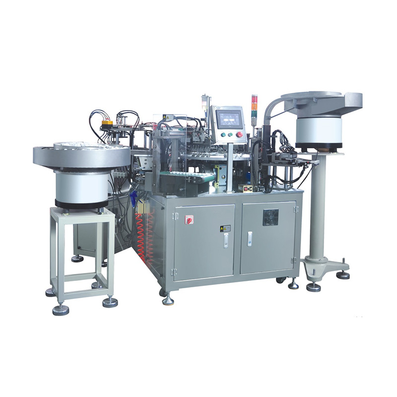
China Zhejiang Taizhou Ambe Trading Co., Ltd. is a manufacturer specializing in the production of medical equipment automation equipment.
Medical devices often rely on parts that are difficult to see, pick up, align, or join consistently. A connector may contain a tiny seal, a catheter hub may need a precisely positioned tube, and a fluid filter may include a membrane that must remain clean and undamaged. When these parts are assembled by hand, results can vary with operator technique, fatigue, and the way components are presented. Medical device assembly equipment helps control those variables through repeatable feeding, positioning, joining, inspection, and process records.
Small-part assembly is not simply a matter of using a miniature robot. The equipment has to match the component’s material, geometry, tolerances, cleanliness requirements, and intended function. A successful system also needs to detect misfeeds and assembly defects before the next operation.
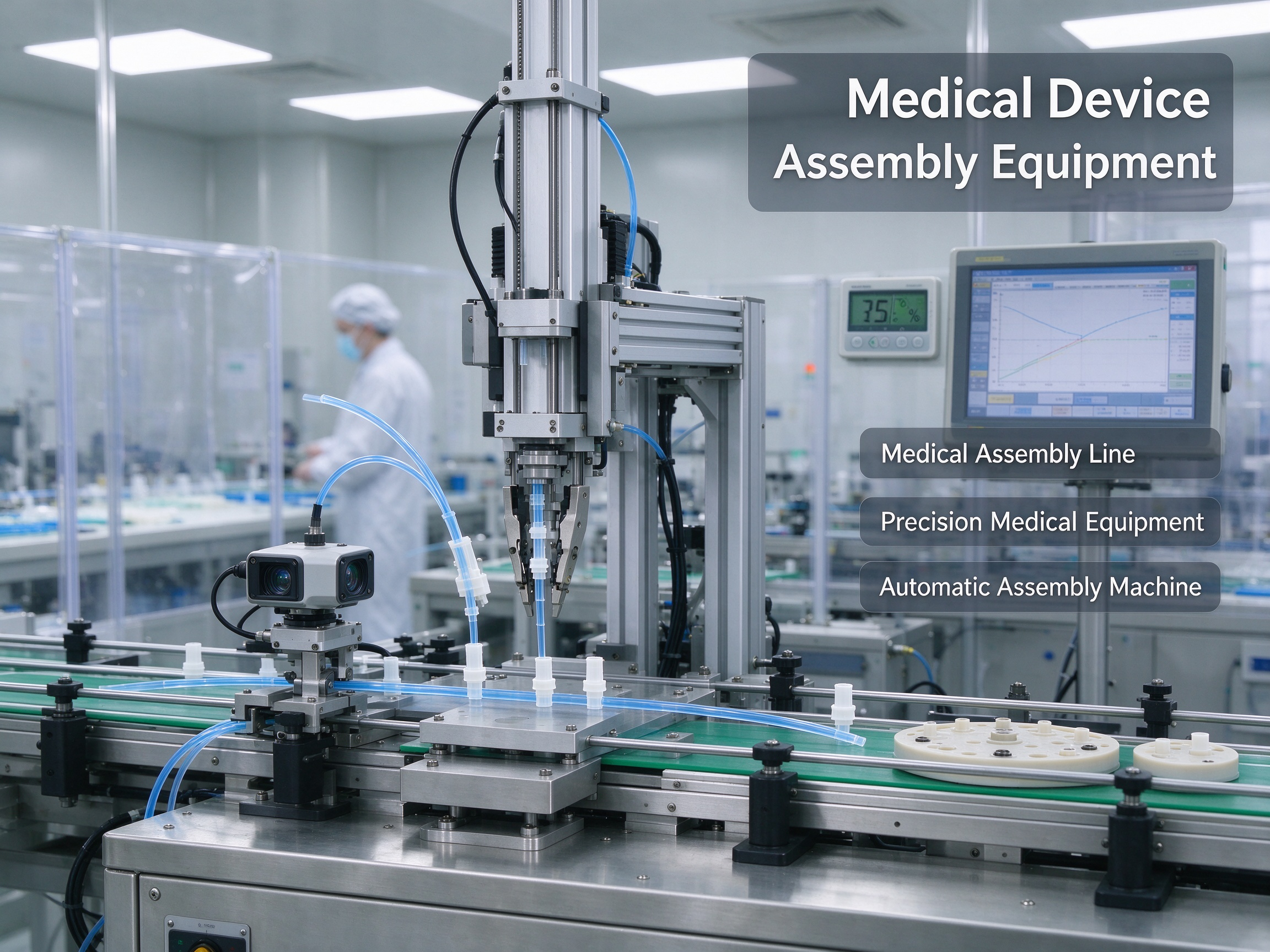
Why Small Medical Device Components Are Difficult to Assemble
Small components create several challenges at once. Their limited surface area gives grippers little room to hold them, while flexible parts can bend or deform under excessive force. Transparent, glossy, or similarly colored components may also be difficult for a vision system to distinguish from their surroundings.
Complexity increases when a part has several features that must line up in a specific orientation. A connector may have a keyed profile, sealing groove, and internal passage. A tiny valve can include a housing, spring, membrane, and moving element. If one feature is rotated or seated incorrectly, the final product may fail a leak, flow, pressure, or functional test even though it looks acceptable from the outside.
Common production challenges include:
- Part presentation: Components arrive randomly oriented, overlap, or stick together because of static, surface finish, or geometry.
- Tight alignment: Tubes, pins, seals, membranes, and housings may need concentric or angular alignment within defined tolerances.
- Material sensitivity: Soft polymers can scratch, stretch, or deform; brittle parts may chip; delicate membranes can wrinkle or tear.
- Contamination control: Dust, fibers, oil, and handling residue can affect products with fluid paths or other cleanliness requirements.
- Limited inspection access: A joint or seal may be hidden after assembly, so the process must capture evidence before it becomes inaccessible.
Identify these risks during process development; equipment cannot compensate for unclear drawings or unstable component quality.
How Automated Feeding and Orientation Systems Handle Tiny Parts
Before assembly can begin, each component must reach the workstation in a predictable position. The suitable feeding method depends on part size, shape, material, and acceptable contact with the component.
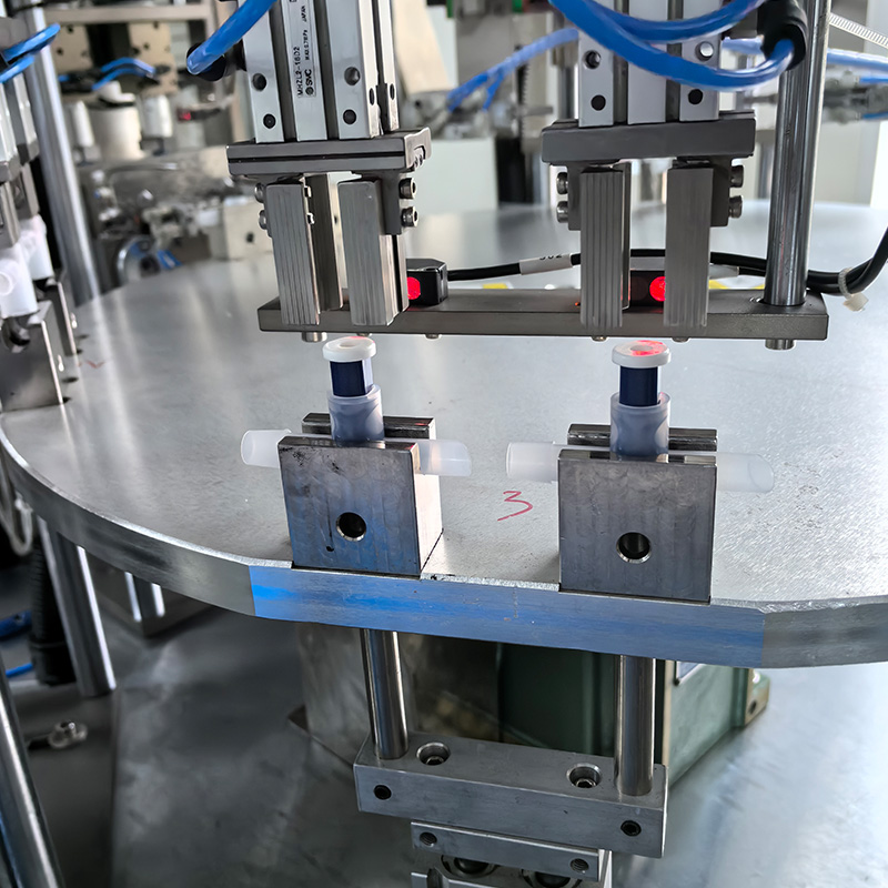
Vibratory bowl feeders are often used for rigid parts that can tolerate controlled movement. Tracks, escapements, and nests guide components into a repeatable pickup position. For parts that may scratch, tangle, or deform, alternatives include flexible feeding systems, tray presentation, magazines, or precision pallets. Flexible feeders can spread randomly placed components across a surface and use a camera to identify suitable pickup points, although transparent or reflective parts may need special lighting and careful image setup.
Orientation features should be designed around the actual part. A keyed nest can prevent a connector from being loaded backward; a presence sensor can confirm that a component reached the station. For very small or easily damaged pieces, reducing unnecessary transfers is valuable. Each extra handoff creates another chance for a drop, surface mark, or orientation error.
Run feeder trials with representative parts and normal variation in dimensions and surface finish. Hand-selected samples may hide problems with mixed lots or parts near tolerance limits. Track misfeeds, recovery time, and damage, not just average feed rate.
Precision Positioning and Gentle Part Handling
After feeding, the equipment must hold components securely enough for assembly without damaging them. The choice may be a mechanical gripper, vacuum pickup, compliant nest, micro-clamp, or custom tooling. There is no universal gripper for small medical parts: suction may work well for a flat rigid piece but fail on a porous membrane, a curved surface, or a part with small openings.
Precision stages and fixtures establish the relationship between mating parts. Depending on the process, positioning may use hard stops, datum surfaces, machine vision, force sensing, or a combination of these methods. A camera can locate a feature, while a fixture provides repeatable support during insertion or joining. Validate vision across expected color, reflection, lighting, and surface variation.
The goal is controlled contact. Excessive gripping pressure can distort a soft seal and produce a leak after release. Too little holding force can let a tube shift during bonding. Test tooling across component tolerances; replaceable inserts can help manage wear and product variants.
Joining Methods for Small and Complex Medical Device Parts
The joining technology should follow the materials, joint design, production volume, and performance requirements. A process that makes a strong joint on one polymer may be unsuitable for another or may introduce heat, particles, or residues that affect the product.
|
Assembly method |
Where it can be useful |
Key process controls |
|---|---|---|
|
Precision press-fitting |
Pins, inserts, hubs, and mating rigid parts |
Alignment, insertion depth, force and displacement limits |
|
Ultrasonic welding |
Compatible thermoplastic housings and selected fluid-handling components |
Weld energy, pressure, time, tooling condition, and joint design |
|
Laser welding |
Selected plastic joints where localized energy and controlled access are useful |
Material compatibility, laser settings, clamping, joint gap, and inspection |
|
Adhesive dispensing and curing |
Components that require bonding or sealing with a qualified adhesive |
Dispense volume, bead location, mix ratio where relevant, cure conditions, and lot life |
|
Thermal bonding |
Compatible polymer parts joined through controlled heat |
Temperature, contact pressure, dwell time, cooling, and deformation |
|
Mechanical insertion or assembly |
Clips, springs, caps, seals, and multi-part subassemblies |
Part orientation, seating position, force profile, and presence confirmation |
These are starting points, not prescriptions; test the selected method with the exact materials and design. For example, adhesive bonding may require attention to cure time and residue, while welding needs a joint geometry that directs energy appropriately. Any change to a material, supplier, tool, or critical setting should be assessed for its effect on the validated process.
One machine may feed a housing, insert a seal, place a tube, weld, and verify the result. Integration can reduce handling and floor space, though fault recovery and maintenance become more important. Modular stations can suit products that change frequently.
Using Sensors and In-Process Inspection to Prevent Assembly Errors
A useful assembly system checks critical conditions while parts are still accessible. Presence sensors confirm that a component is available; vision systems check orientation and visible features; force and displacement monitoring can identify abnormal insertion behavior. Depending on the application, other checks may include weld signatures, adhesive dispense monitoring, dimensional measurement, or electrical continuity.
Link inspection to a defined response. A missing seal or out-of-range insertion force should trigger a stop or diversion under the approved control plan. Alarm limits need to be established through engineering studies, because limits that are too wide may miss defects and limits that are too narrow can create excessive false rejects.
Not every defect is visible to a camera. A joint can look complete but still leak; a tube can be present but partly blocked. Functional tests may therefore be needed after assembly, such as leak testing, flow testing, pressure testing, or electrical testing, depending on the device. Test methods and acceptance criteria should reflect the product’s design inputs and risk analysis.
Maintaining Cleanliness and Contamination Control
Small components can be affected by particles that are difficult to see. Equipment design should consider the product’s cleanliness requirements, the production environment, material compatibility, and how tools are cleaned. Smooth, accessible surfaces can simplify cleaning; lubricants, exposed wear points, and particle-generating contact should be evaluated carefully.
Some assemblies require controlled environments, but the required conditions depend on the device and its manufacturing process. A cleanroom classification alone does not establish that an assembly system is suitable. Consider operator access, air movement, component transfer, maintenance, cleaning agents, and particles from moving mechanisms.
Where fluid paths, membranes, or patient-contacting components are involved, contamination risks should be addressed within the manufacturer’s documented quality system. Equipment suppliers can explain machine materials, cleaning access, and compatible maintenance practices, but the device manufacturer remains responsible for establishing applicable cleanliness requirements and verifying that the process meets them.
Traceability, Data Collection, and Process Validation
Automated equipment can collect more than a simple pass-or-fail result. Depending on the design, it may record product identifiers, component lots, station results, force curves, weld parameters, inspection images, alarm history, and equipment status. These records can help engineers investigate recurring failures and determine whether an issue is linked to a component batch, machine station, or process change.
Data is useful only when reliable, linked to the correct unit, and properly controlled. Define which parameters are critical, who may change recipes, how software revisions are managed, and what happens when a record is incomplete. Where electronic records are used for regulated production, applicable recordkeeping and data-integrity expectations should be assessed for the market and quality system involved.
Installation and process qualification should be planned around the machine’s intended use. Teams commonly assess installation, operating ranges, repeatability, alarms, changeover procedures, and the ability to produce conforming parts under routine conditions. The exact validation approach depends on the process and regulatory context. A supplier factory test helps, but does not replace evaluation with the customer’s parts, specifications, and production conditions.
How to Select Equipment for Your Component and Production Needs
The best system starts with a clear understanding of the assembly task. Before requesting quotations, prepare sample parts, drawings, critical dimensions, material specifications, expected volumes, and known failure modes. Describe what the machine must assemble and how a successful unit will be verified.
Compare suppliers on more than nominal cycle speed. A fast machine that needs frequent manual recovery may deliver less usable output than a slightly slower, stable system. Useful questions include:
- Can the supplier demonstrate feeding and assembly using representative parts across normal dimensional variation?
- How does the machine detect missing, reversed, damaged, or incorrectly seated components?
- Which process parameters are monitored, stored, and protected from unauthorized changes?
- How quickly can the system recover from jams, replace tooling, and change between approved variants?
- What support is available for installation, training, spare parts, maintenance, and process development?
Request a factory acceptance test using the production sequence. Define how cycle time, yield, false rejects, changeover, and measurement results will be calculated. Ensure rejected parts are contained and unresolved alarms cannot be bypassed accidentally.
What to Confirm Before Moving Into Production
Before releasing a medical device assembly process, confirm that the equipment consistently handles the smallest and most delicate components, achieves the required alignment and joining performance, and detects the failure modes identified during risk assessment. Review trial data, inspection results, maintenance access, and operator procedures with the engineering and quality teams.
Confirm applicable specifications and acceptance criteria for the product, market, and site; a generic machine specification is not proof of compliance. Keep the approved setup, critical settings, and change-control process documented, then re-evaluate the process when materials, components, tooling, software, or production conditions change.
Reliable small-part assembly comes from matching the equipment to the part and backing that choice with measurable process controls. Feeding, positioning, joining, inspection, cleanliness, and traceability should work as one coordinated system. When each stage has a defined purpose and a way to verify its result, manufacturers can improve consistency while making production problems easier to detect, investigate, and correct.